
We first showed you how to multiply clocks using only digital logic. Then we moved on from the hacks to a more useful application - dividing clocks using digital logic.
Today, we throw off our digital shackles completely - we're going to do a brief overview of PLLs, Phase Locked Loops.
The Theory of the Phase Locked Loops
How fast is your computer?
Maybe I'm the first one breaking this to you, but there isn't a 4 GHz oscillator running your processor, along with separate clocks for the various buses hanging off your CPU. This is where a Phase-Locked Loop (and/or its cousin the Delay Locked Loop) comes into play.
One application of a PLL is synthesizing various, phase related frequencies from a known frequency. Yes, for our purposes, that means we can reliably multiply clocks.
For an excellent overview of PLLs, please see Kenneth Finnegan's excellent theory and application overview on Youtube. It uses the (getting on in years, yet still very useful on the breadboard) 4046 PLL. Also read his accompanying blog post, which includes schematics.
Elements of a Phase Locked Loop
We won't go too deep into the theory of PLLs, but we will cover the three major parts:
- Phase Detector
- Loop Filter
- Voltage Controlled Oscillator (technically, other oscillator types are possible)
These parts are generally broken out on whatever PLL you choose to use. That is, you control the connections of the outputs of one stage to the inputs of another.
Warning - these parts have more analog than usual if you come from a digital or programming background.
Be prepared to read through the data sheet a few times to figure out the vagaries of your choice of chip. Often, PLLs will include charts which will help you with component selection for the passives you'll need to build your circuit.
Remember, a PLL is an oscillator which uses feedback to increase or decrease its own frequency. That is, it uses feedback cleverly derived from its own output signal to 'lock' to a signal.
Now, onto the three parts of a PLL.
Voltage Controlled Oscillator
Oscillators are fun, but oscillators which can be easily controlled to oscillate at a different speed? More fun.
That's where the voltage controlled oscillator comes into play. Inputting a voltage to the VCO excites the oscillator and changes the instantaneous frequency of the VCO's output.
From that perspective, a VCO is useful on its own. When you first start playing with your PLL, try connecting a potentiometer between +5V and the input of your VCO (well, if you have a 5v tolerant part), and measure the output on an oscilloscope.
You'll have 120 seconds worth of fun; I promise!
Loop Filter
Filter design is the most annoying part of the PLL circuit.
Let's skim past this part without delving too far into the weeds (many, many PhDs could be earned on this topic). For the purposes of a frequency multiplier, just know you'll want a low pass filter.
Aim for something with a bandwidth around 1/10th of your VCO center frequency, and scale accordingly: theory is great, but expect to do a little experimentation.
Even the low pass filter itself can be needlessly complex - active (which Op-amp should I use?) vs. passive? How many orders?
When playing with a 4046, a simple first order low pass filter is just fine for experimentation. If you pick another PLL and want to get started quickly, it's best to try to find an App Note for your part which deals with similar frequencies. Remember, the first law of engineering is: "First make it work, then make it pretty".
The basic tradeoff with your low pass filter in a frequency multiplier is this:
- If you increase the bandwidth, the stability suffers - you'll lose the lock on your signal more easily.
- If you decrease the bandwidth, actually achieving lock will take longer... if it happens at all.
Seriously - read the data sheet (multiple times!), note the charts which help you pick parts, and don't be afraid to experiment.
Phase Comparator
Some part of a PLL circuit actually needs to 'tell' the VCO to oscillate (read: present it a voltage). That's where the phase comparator comes into play.
At its most basic level, a phase comparator can be an XOR gate. An XOR, of course, will only be 'high' when an odd number of inputs are high.
This is great for some applications, but one potential downside?It has very little sensitivity to harmonics of your input signal. (And, yes, these can be exploited by a clever designer for some applications).
Either way, a voltage '1' will excite the VCO and change the frequency when presented to the VCO. An XOR is very useful for this.
For digital logic, we generally aim to use a phase comparator based on 'edges', just like those square waves and flip-flops which play so nicely together.
Certain builds can even introduce a third state into the mix - reducing voltage below zero. Consider this: since the comparison frequency can be before or after (in phase) of the input frequency, this can signal "too fast", "too slow", or "just right" to the VCO.
PLL Frequency Multiplication
So, you've got a PLL, you've got an input frequency, and you're ready for a breadboard. Great. Now, let's do something practical with it.
PLLs have tons of applications - recovering clocks from a signal, locking onto frequencies received from an antenna, even cleaning up a dirty clock signal with an imperfect duty cycle.
For this application, I wanted to multiply the frequency of an input signal by 14. That is, I wanted to take in 1.789772 MHz and spit out 25.0568 MHz.
I already told you that the PLL, as wired, will try to react to the difference between two signals. The PLL also controls the signal coming out of the VCO.
So, imagine what would happen if we divided the VCO output by 14 and fed it into the comparator?
Exactly what you'd expect - the PLL would receive a bunch of "go faster" signalling internally, as it would be trying to match .223721 MHz to 1.789772 MHz at "time 0".
Those signals would excite the VCO, and our instantaneous frequency would increase. Slowly, it would converge on 25.0568 MHz... because then the PLL would be 'seeing' 1.789772 MHz at the phase comparator since we would be dividing that 25.0568 MHz by 14.
Verify it with an oscilloscope, or hook it up to whatever needs the multiplied clock!
PLL Frequency Multiplication In Practice: Build it in the Lab
A disclaimer: take the schematic with a grain of salt, and always verify my work. I can't even guarantee I transcribed it perfectly from my breadboard.
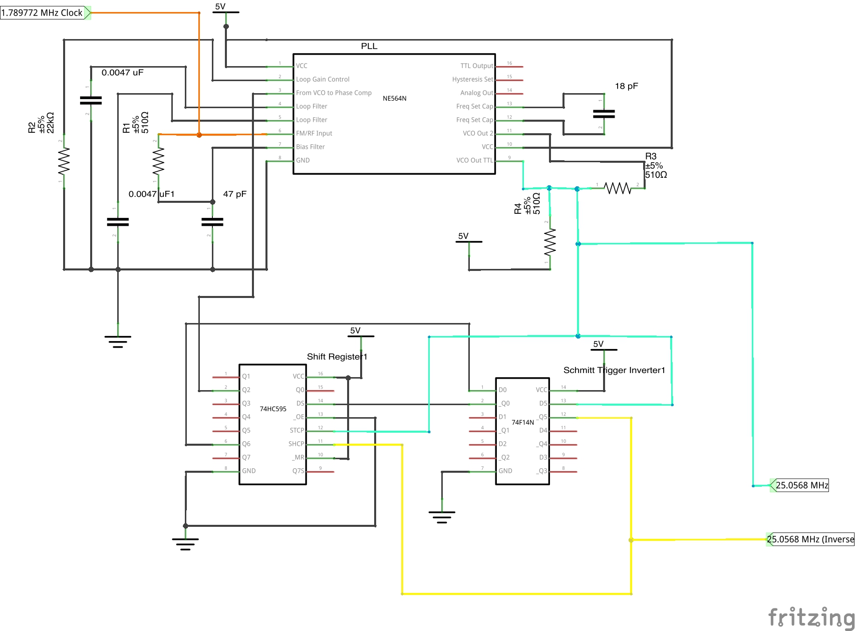
The 18 pF capacitor, the two 0.0047 uF capacitors and the 22 kOhm resistor are the most important (especially that 18pF capacitor). The two 0.0047 capacitors are your filter - adjusting those will change how quickly your circuit will lock to 25.0568 MHz.
Note, too, that you might need to change which pin on the 595 you feed back to the PLL. Q0 through Q7 will have 7 different phases, so you will get better results with some, and others won't allow the PLL to lock.
Your Turn to build the PLL circuit?
We successfully produced a clock compatible with both VGA and NTSC with this project. Eventually we used it in this Hackaday contest entry to produce a video card.
This entry shows the whole thing working, with a similar circuit to the one posted above. So, yes, it worked!
So, let us know if you're able to create your own clock multiplier using this information. Good luck, and have fun!
