
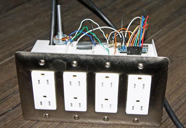
I built an Arduino real time frequency analyzer with a microcontroller which doubles as a Christmas light controller.
You can take line in from any source in one of 8 audible octaves. Notes activate a relay providing AC power to a plug, which in turn light up a strand of Christmas lights for each frequency band.
It uses FHT (Fast Hartley Transform) as its real time frequency analyzer algorithm, not the more commonly known FFT (Fast Fourier Transform) to do its real time processing.
Controlling Christmas Lights with an Arduino
We've had music reactive displays and color organs for a long time – this much is true. I didn't like the previous implementations I had seen.
By far, the most common way to control Christmas lights is manually timing lights by using software like Vixen or Light O Rama. That's fine - I just didn't want to learn a new piece of software.
Thus this project was born - 8 plugs (but certainly expandable) controlled by any random song you feel like playing through the line in.
What Do I Need to Build the Arduino Frequency Analyzer?
- A microcontroller - I built it with an Arduino Nano. Use whatever you like, just make the modifications. Let's call it $20.
- An 8 channel relay board from eBay - you likely want to get solid state relays since you'll be switching a lot. (Trust me here.) $15 - $25 depending.
- A 10k Ohm logarithmic potentiometer - also known as an Audio Potentiometer. $2.
- Various hookup wire - you should use insulated wire for the signal hookup to the relay board inside the 4-gang box. $2?
- Generic 4 Gang electrical box - get a deep one, from any big box store. I paid like $6.
- Generic 4 Gang faceplate - isn't my aluminum nice?. Another $3.
- Generic plugs to fit the faceplate - we got 'designer' plugs, but you can get rounded. $8.
- 5-10 feet of Romex for hookup wire - $10 maybe.
- Headphone jack (like on your iPod) - get mono, unless you are more ambitious than me. Maybe 50 cents? (I pulled it off something.)
- 2 100k ohm transistors. See below.
- 1 10 uF capacitor. See below.
- 1 4.7nF capacitor (for decap - if you have issues with interference, toss a bunch more in there). All the components, $1 total.
- Extension cord or power cable to sacrifice. $5
- Wire nuts. $3
- A promise you know what you're doing- the first half of the project you might fry a component, the second yourself - you assume responsibility. (Priceless!)
- Optional - 8 strands of LED Christmas lights (assuming you don't have them. We had 4, so I assume you might have some.). $5 - 8 each.
A number of the Amazon links are tied to our affiliate account; we appreciate your support if you buy through them!
If you're thrifty, this will cost ~$75 - $130.
If you've got a bunch of stuff already? You're getting off cheap.
Building the Input Circuit and Low Voltage 'Stuff'
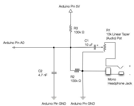
Here's my input stage.
Do NOT hook your headphone jack straight to a uC. It has alternating voltage on it, and you might get blue smoke instead of a voltage reading.
Here's how I built it:
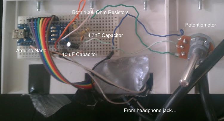
Here's a closeup of the breadboard from above.
FHT Software for Arduino
You can use a ton of algorithms here to analyze the input to your Arduino - FFT (Fast Fourier Transform) being the most famous. I went slightly more obscure with FHT, or Fast Hartley Transform.
I played with a few libraries, and ended up using the one from Open Music Labs - I highly suggest checking out their benchmarks - FHT is pretty much as fast as you'll get here, and with an 8 bit microcontroller you need fast.
The code is adapted from the demo code provided by OML, so I am greatly in debt. My neighbors and I thank you.
Here's my code (zip, ino file): FHT_XMas
Dry Run of the Arduino FFT Frequency Analyzer
Okay, double check your connections and plug it in. Load the sketch onto your Arduino. Open a serial monitor at 9600 bps and you'll start to see numbers scroll by...
Advanced: I have a line in the code, starts with - int oct_bias - you can set those to 0 if you want to see raw data, but you're aiming for around '0'. In most cases, the defaults are fine. Otherwise, tweak and try to get them near 0.
- Plug any audio source into the Arduino - well, any headphone jack.
- You should see the numbers jump when you play audio (if you don't? First check the audio pot is open. Turn it.).
- You can adjust when the relays are active using the #define THRESHOLD command. Change it there if the potentiometer isn't enough for you.
AC Voltage Warning
If you aren't comfortable working with line voltage do this under the supervision of someone who is. Always double/triple/ and quadruple check for shorts and missed connections before plugging this in.
Okay, it's game time. Step one, wire up your relay board. Most relay boards you buy pre-made are active low. If yours isn't FIND/REPLACE the HIGHs and LOWs in my relay code (near the bottom). My software assumes you will use digital pins 3 through 10 on your microcontroller - so signal pin 3 should go to the relay you want controlled by bass. Then wire the rest, and provide power and ground form the Arduino.
Hopefully you noted my comment earlier - you should use insulated wire (using some of Romex would be fine - but you probably want stranded core), rated at at least the peak voltage inside the container.
This project isn't UL listed or anything, but you want to protect what you've got in the box. So divide it if you can, and keep low voltage routes away from high voltage ones. The relay board should be in the electric box, and the Arduino should be outside!
Test the code again. For mechanical relays you can hear a click, and for most SSRs you should see a light denoting the channel is on. If so, unplug the Arduino and it's time to wire for higher power!
Wiring Mains Voltage
Break off the tabs on the 'hot' side of your plugs (line). (In the US, that's the side WITHOUT ground).
- Hook up your grounds to the extension cord (run it into the box), keep it tight - make sure to test fit it in the box.
- Hook up the commons (load) (the white wire in many jurisdictions, check local codes/ask a friend if you don't know), using pieces of ROMEX and wire nuts.
(A note: don't be snarky - I know you could do the same with load. However, you want that wire to go directly to the relay - if you wire hot directly to the plugs, there will still be potential on the plugs when the relay is switched off!) - Now, hook up hot! This will change based on the relay, but you basically want 8 channels wired together INTO the relay, and a single wire FROM the other side of the relay to each of the 8 line terminals (Again, that's the isolated side on your plugs).
You now need to push it back together.
Just like replacing a switch in a doubly tapped circuit, check if any wire is exposed (your call on how to re insulate it). Carefully slide them down and screw them in. Put the plate on top.
Your ground is working, right? Check again, especially if you have a metal faceplate.
Power Delivery - Why You Should Use LED Strands with Relays
Most pre-made solid state relay boards won't switch more than 2 amps, and even most boards of solid state relays switch just 10. However, your practical limit when you have 8 outlets butts up against total branch power in the US.
For most rooms, you've got 15 amps total to play with - a total of only roughly 1700 watts.
Subtract power for anything else you have running on that circuit - computers and a stereo, perhaps? Additionally, you're switching this power through a pretty shallow box - you need to consider the heat build-up.
What to do? Grab some 2 or 4 watt LED Christmas light chains.
Even if you put 2 strands on each plug, worst case you're only talking 64 watts total - about the same as a single incandescent bulb! You've also spread the heat across the 8 relays instead of pushing 64 watts through a single one.
(Note that common 220 watt incandescent strands mean 1760 watts with just a single strand per plug, which might be enough to trip your breaker at a particularly loud section of music. DON'T TRY IT.)
Does the Arduino Frequency Analyzer... Analyze?
If you've quadruple checked, and doubted everything I said and checked elsewhere on the internet, it's go time.
- Plug in your Arduino and 8 LED strands and bulbs.
- Turn on the music.
- Plug it into a GFCI outlet (ask around if you don't know), maybe with a surge protector
- Oh, keep a fire extinguisher nearby!
Let there be light! (And if not, UNPLUG it before debugging.).
Here's a shot of mine working with the real time sounds of Beethoven's 9th Symphony. Yes, it's a 7-bit FHT in the video - one of the relays on my board was broken. It's another reason to get Solid State Relays to switch those LEDs.
Like it? Hate it? Improved it? Let me know, by email.
